My interactive LED strip
My old light strip recently broke. Instead of buying a new one, I thought I’d try making my own improved version.
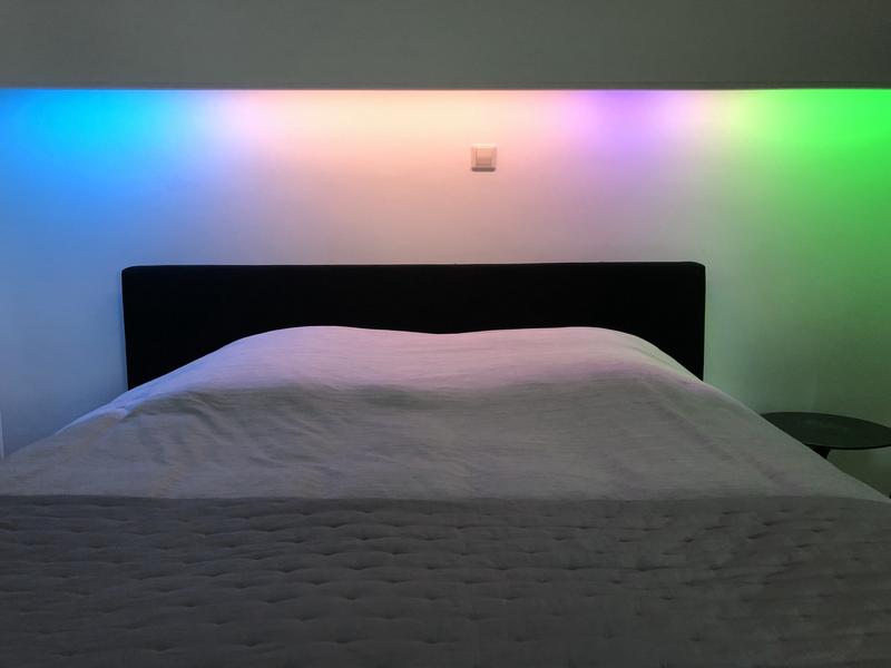
It has several different “widgets”, from left to right:
- a 2 hour weather forecast (blue means rain, yellow means sun, quite straightforward)
- a timeline of upcoming calendar events in the next 4 hours, syncs with my phone
- my stock portfolio (green means good, red means bad)
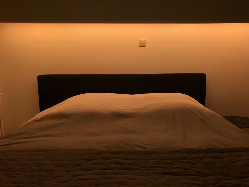
It is also possible to use the strip as any ordinary RGB LED strip via a simple web UI and there’s “night mode” that turns off the blue LEDs.
Architecture
There are two parts to this project: the controller that talks directly to the LEDs, and the server that fetches weather, stock and calendar information and passes that information on to the controller.
The LED strip + controller consists of a few different parts:
- A 4 meter 30 LEDs/m WS2812B strip. This is a 5V LED strip that can be cut to length. The thing that is special about this strip is that it allows each individual LED to be accessed via I2C.
- An ESP8266. This is a cheap microcontroller with built-in WiFi.
- 3.3V to 5V logic level converter. The ESP8266 expects 3.3V, but the LED strip expects 5V. This logic level converter will act as a middle man between these two components and convert 3.3V signals to 5V and vice versa.
- A 5V 8A power supply. Each of these LEDs can pull up to 60mA. With 120 LEDs, that is 120 * 0.060 = 7.2A.
- A big 1000mF capacitor connected to the 5V rail, to prevent sudden power spikes from damaging the ESP8266 or the LED strip.
These parts cost me ~€26 in total.
One problem I ran into was the voltage drop after a few meters. 7.2 ampères through a thin copper wire means that you lose a significant amount of voltage over a few meters. This meant that the last LEDs in the strip got a red-ish tint as the blue LEDs became dimmer (this has to do with the difference in forward voltage between red and blue LEDs; blue LEDs require a higher voltage to turn on than red LEDs). This was easily solved by running two extra thin copper wires (one for +5V and one for GND) along the LED strip and soldering them to the other end of the strip.
The controller
The ESP8266 runs a very simple HTTP REST API that allows you to set the LED color of ranges of the strip. It is very dumb and does not do anything other than turning some LEDS off and on. The code is available here.
The server
The server that fetches weather, calendar and stock info was written in Go and is available here. It is easy to create new modules (see the weather widget, for example). The server will automatically give each module the chance to update every 15 minutes. There is also a small web server running on port 8080 that allows you to control the different modes of the strip, however its interface is very rudimentary, ugly and not yet finished.
Future possible ideas
- Use MQTT instead of HTTP
- Adapt brightness depending on surrounding light
- Make a wake-up light (these cost $140 on Amazon)
- Philips Hue integration
- IFTTT integration
- Extra widgets
Things I would have done differently
If I had the chance to start all over again, I would probably use SK6812 LEDs instead of WS2812B. The WS2812B’s have 3 LED channels: one for red, blue and green. This is great for most colors, though they have trouble recreating warm whites. SK6812 strips have a 4th LED channel for warm white LEDs, so they are much better at creating warm white light. They are just ~€1 extra per meter, so I would probably choose these if I had to start all over again.